Data at my fingertips!
In this tutorial, we are going to read data from various sensors, and use it to trigger certain actions. We will learn the analogRead, analogWrite functions in this tutorial too.
Sensors that will be covered
- Potentiometer
- Light Dependent Resistor/Photoresistor
- Ultrasonic Distance Sensor
- TMP36 Temperature Sensor
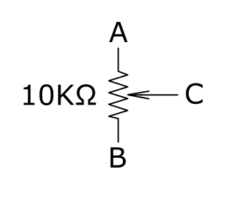
Reading from potentiometer
The potentiometer is essentially a variable resistor. But instead of having 2 pins, it has 3 pins. The potentiometer that is provided in the kit is a 10K Ohm potentiometer, which means that when the knob is turned fully to one end it is 0 Ohm, while at the other end it is 10K Ohm.
Potentiometers are used frequently and comonnly on electronic devices. A simple example would be the volume knob on speakers, or the light dimmers in your houses!
This is the potentiometer that we will be using in this tutorial:
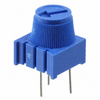
It is the Bourns 3386F Potentiometer that can be found here
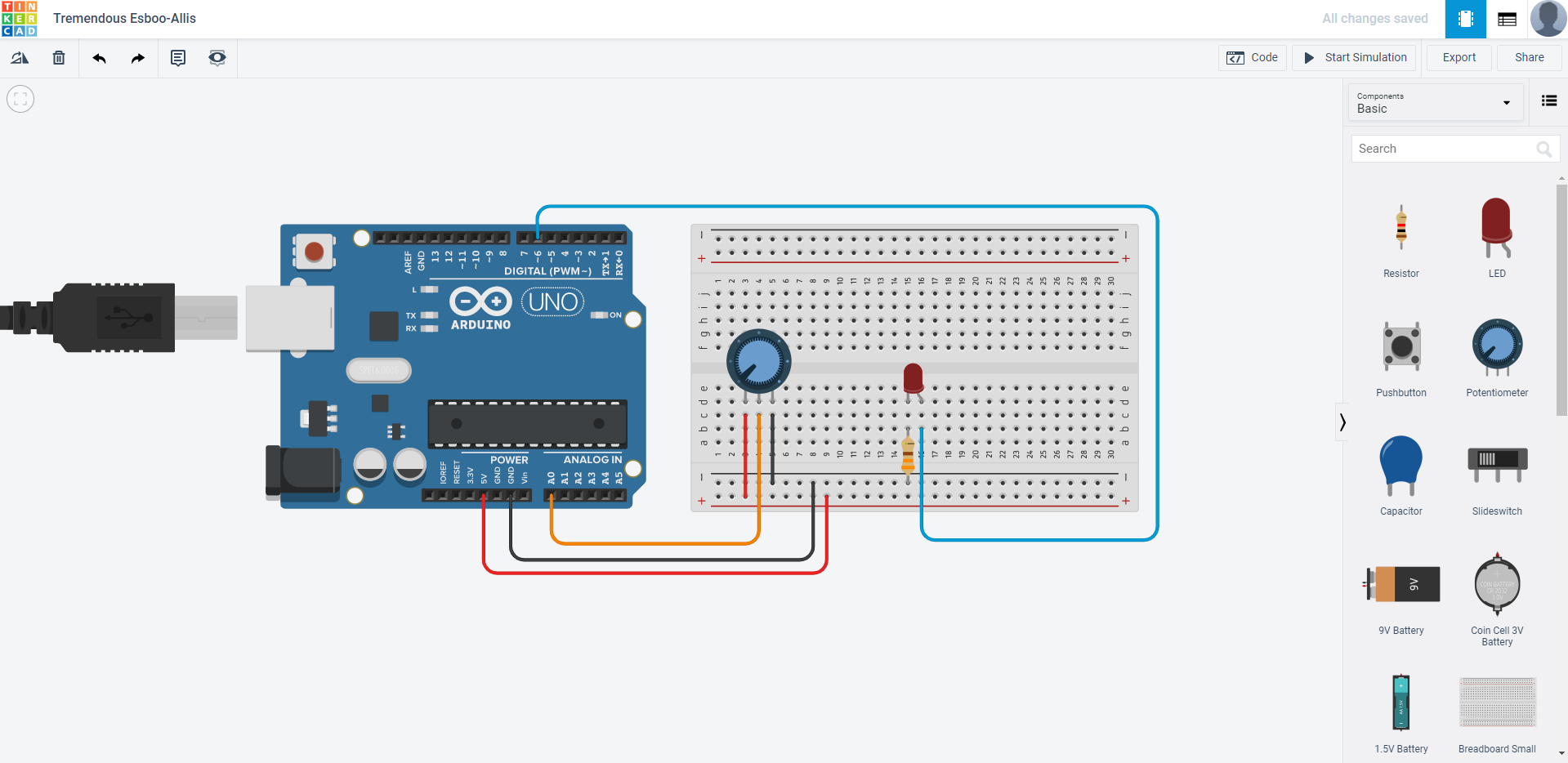
Let us fire up TinkerCAD, create a new circuit and configure your circuit like this:
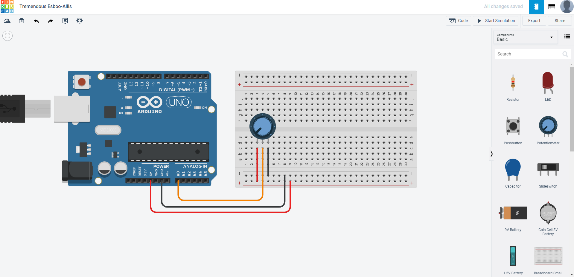
Note that the potentiometer in TinkerCAD and the one provided in the kit is different, as they are different types of potentiometers, but they serve the same purpose and would not have any difference. Next up, in the coding section, we would want to program it such that the serial monitor outputs the reading of the potentiometer.
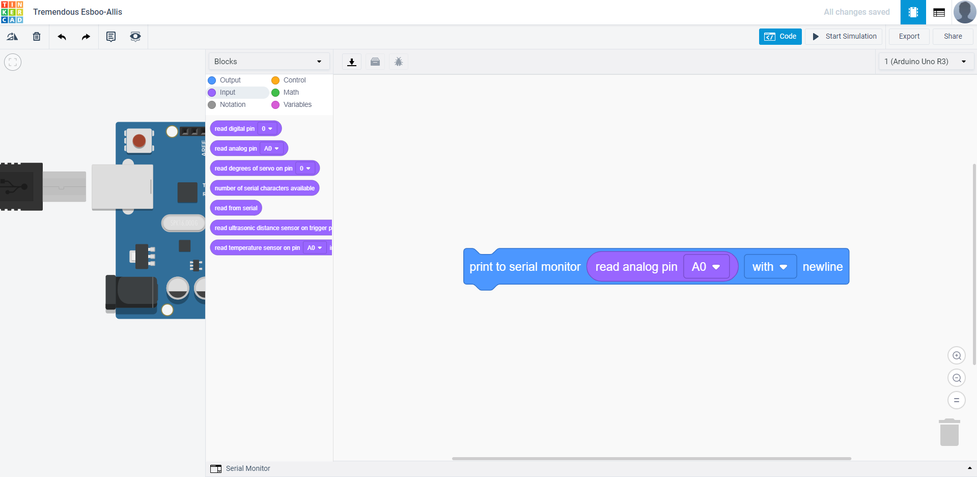
After you are done with the circuit and code, simply run the simulation and open the serial monitor. As you twist the knob of the potentiometer, you should see the number change from 0 to 1023. Why this specific number? Well… Inside the SSTuino’s chip, there is a Analog to Digital Converter, also known as ADC that has a resoloution of 10 bits. The higher the resoloution, the more precise the measurement is. If you use your calculator and then type in 2 to the power of 10 you will get 1024, which is the number of reading that you will get.
Copy this circuit over to your SSTuino board setup.
NOTE: To prevent damage to your computer or the components, please disconnect all power from the SSTuino board when you are wiring up your circuit!
In your Arduino IDE, once you have uploaded the code, apart from opening the serial monitor, you can also open the serial plotter. It outputs the results to graphs.
Speed Control
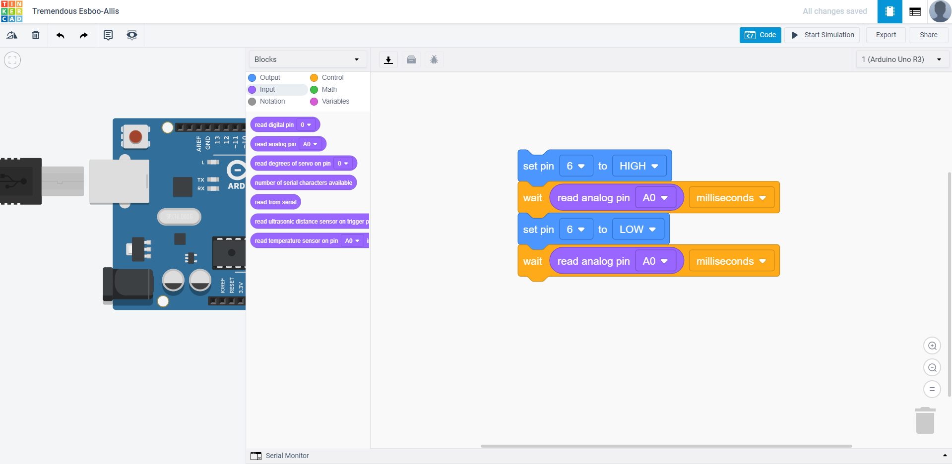
Since we have managed to get a reading from a analog pin from the SSTuino, we are going to make use of the reading to alter the blinking speed of an LED. We are going to first fire up TinkerCAD and edit the circuit to something like this:
For the code, we are going to use the blink code and edit the delay() function. What we are trying to achieve is that when I turn the knob of the potentiometer, the speed of the blinking of the LED changes.
This is the result I should get:
Copy this circuit over to your SSTuino board setup.
NOTE: To prevent damage to your computer or the components, please disconnect all power from the SSTuino board when you are wiring up your circuit!
In your Arduino IDE, once you have uploaded the code, apart from opening the serial monitor, you can also open the serial plotter. It outputs the results to graphs.
SSTuino controlled dimmer
Next, we will use the SSTuino’s PWM output function to control the brightness of the LED. On other pins, you can only turn the LED on or off. There are some pins with the wavy ~ sign, which means that it can output PWM signals. With digital electronics, it requires a bit of a trick to control something with analog means.
PWM stands for Pulse Width Modulation. The pin would output a series of square waves, and depending on the duty cycle, adjusts the width of the square wave. What it essentially does is that it turns on and off the component very quickly, such that our eyes cannot see the difference. In the diagram below, you can see how the duty cycle is adjusted by changing the width of the square wave. When the duty cycle is 0, it turns off the component. From 0 to 100, it gradually increases the intensity, and is a full power when at 100% duty cycle.
To read up more about Pulse Width Modulation on Arduino, check out this link here
For this exercise, we will use the same circuit and just edit the code:
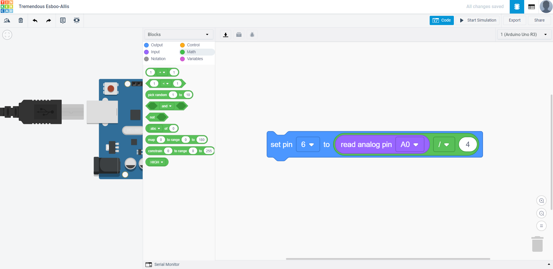
I divide the input by 4 as the range of the PWM output is only from 0-255, which means that it is 8-bit.
This is the result I should get:
Copy this circuit over to your SSTuino board setup.
NOTE: To prevent damage to your computer or the components, please disconnect all power from the SSTuino board when you are wiring up your circuit!
In your Arduino IDE, once you have uploaded the code, apart from opening the serial monitor, you can also open the serial plotter. It outputs the results to graphs.
Beep Beep!
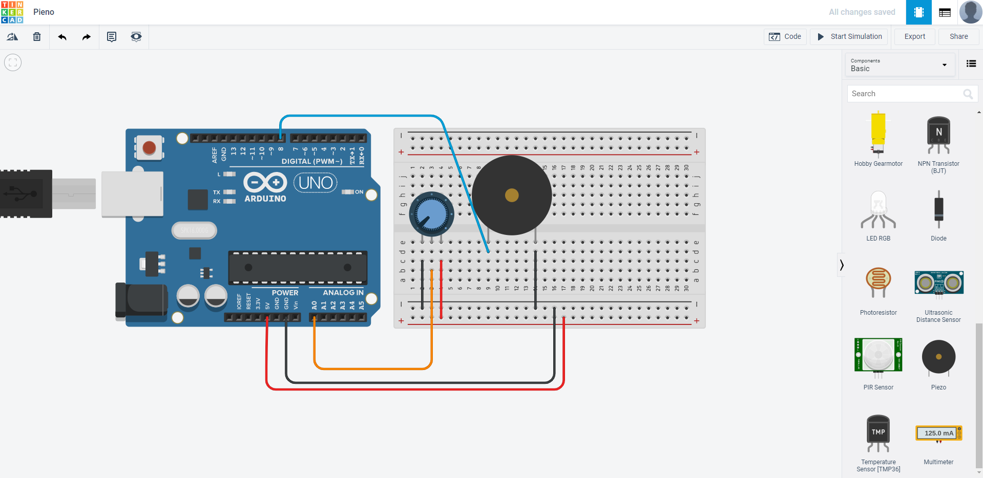
Let us play some tones with the SSTuino! We are now going to insert a piezo element into our circuit. Configure your circuit like this:
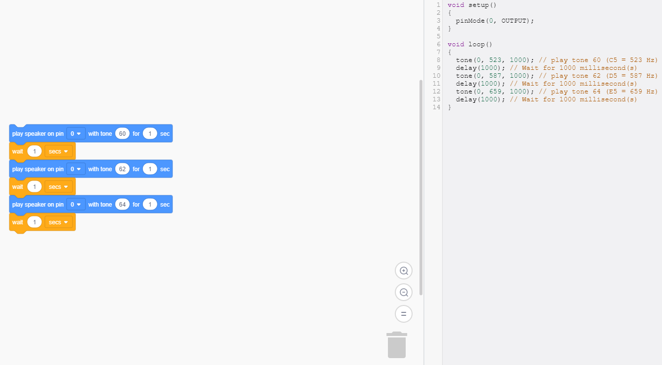
I am going to play 3 tones on the harmonic scale. Can you play up to 1 full scale? (Do, Re, Mi, Fa, So, La, Ti Do!)
Pieno
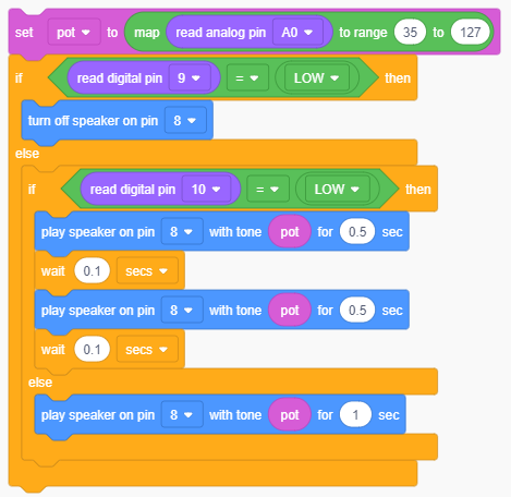
We are now going to use the potentiometer to control the tone of the speaker. This means that as you turn the knob on the potentiometer, the pitch of the speaker will change. With the same circuit as the previous exercise, we are going to tweak the code for the Pieno.
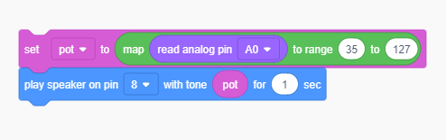
First, we will need to create a new variable called pot. In this exercise, we are going to introduce to you another function: map to range. What basically happens is that the input and output range will mostly be different. In this case, the potentiometer has a range from 0 to 1023, but the speaker has a output range of 35 to 127. By mapping the range, we can make sure that when the potentiometer is at one end of the input range, the speaker is definitely also at one end of its output range.
After you have tried this out, run the simulation and create your own music!
Enhancing the Pieno
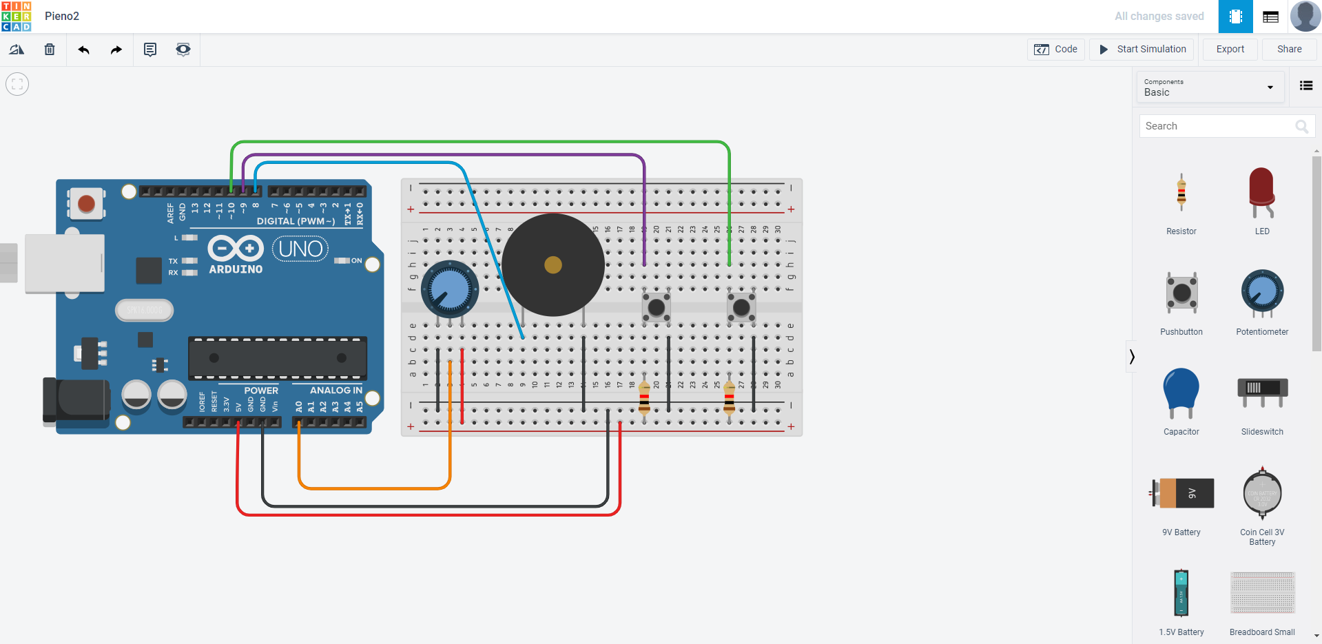
Would it be possible to add more functions to the pieno? Sure thing! Let us add 2 more buttons to the circuit as shown:
These will be the two functions that we will add:
- A button to stop the music
- A button to make the tone beep intermittently
A slightly smarter light sensor
For this exercise, we will be going back to the Light Dependant Resistor (LDR)/photoresistor. Previously in this tutorial, we managed to try out the photoresistor. Now we are going to make use of it as an input for the SSTuino to trigger something! You may remember that the purpose of the photoresistor was not really significant or useful, as it made the LED brighter when the environment was bright. But with some programming, we can make it work properly!
Let us move into TinkerCAD and create a new circuit, something that looks like this:
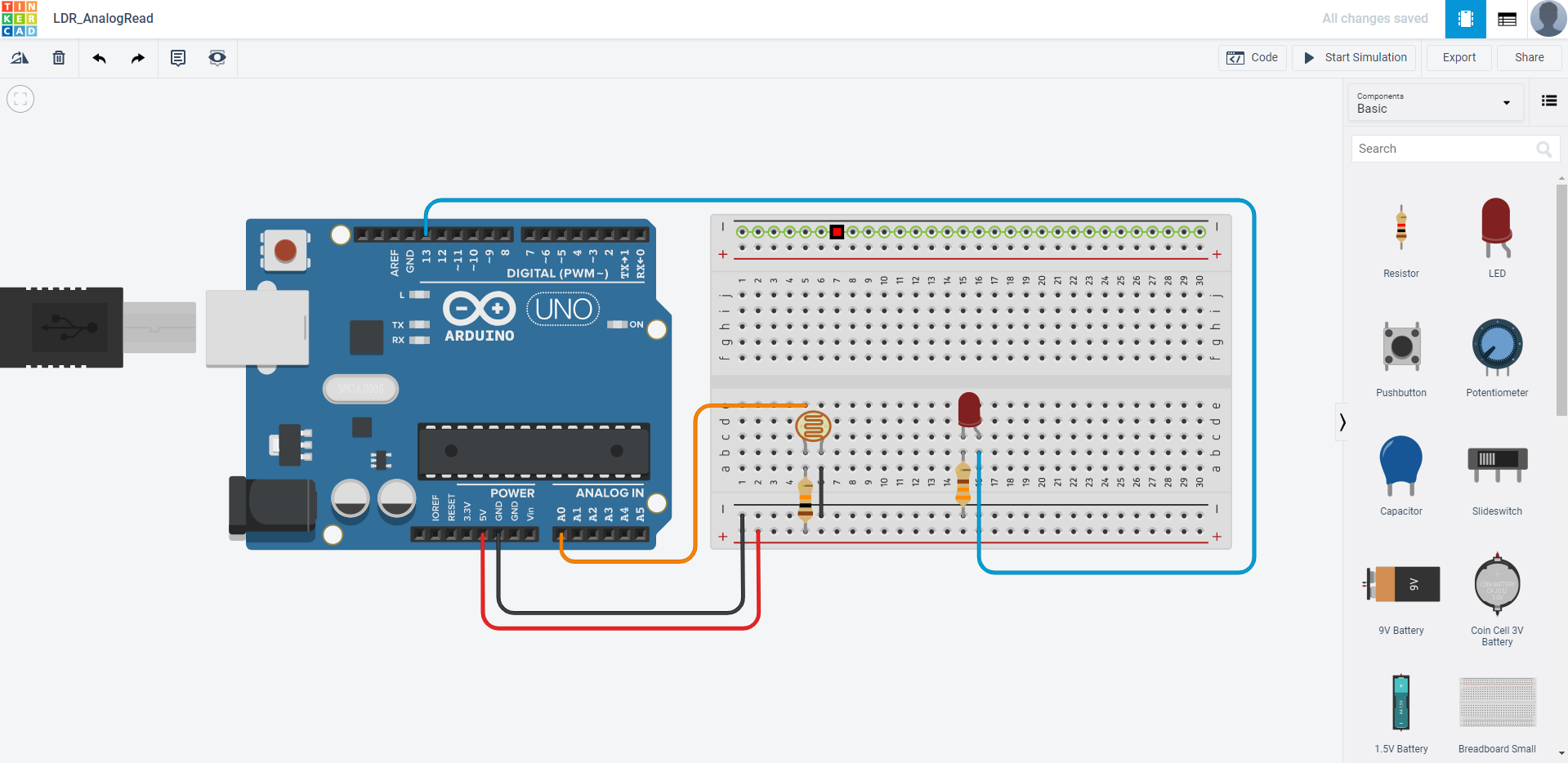
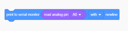
We will read the photoresistor value from the analog pin and output it to the serial monitor.
When running the simulation, open up the serial monitor. The result should look something like this:
While I change the light intensity of the LDR, the readings also change.
Now let us make it useful. We would want to make it such that when the environment darkens, the LED will light up. To do so, we edit our code to something like this:
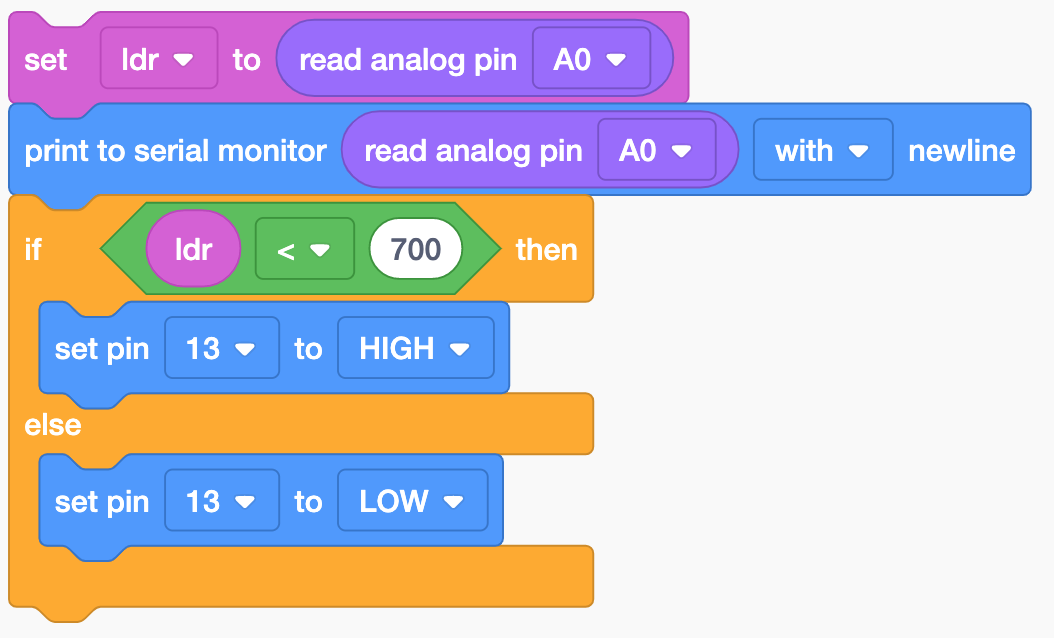
In the if statement, the value where your LDR detects that the environment is dark varies. You may have a different value for your circuit and you will need to edit the value.
Ultrasonic Sensor
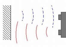
The ultrasonic distance sensor uses ultrasonic waves - a very high pitched sound that we cannot hear to measure the distance it is from an object. It is in a transducer configuration, where the transmitter and reciever is on the same sensor.
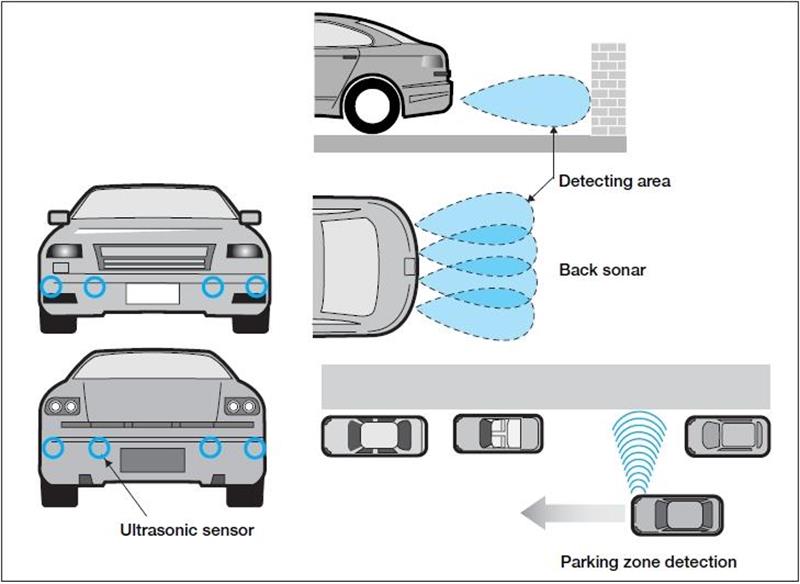
One of the most common uses of ultrasonic distance sensor is in the automotive industry. They are usually used as reverse warning sensors but are increasingly used in self-driving vehicles, like Tesla’s Autopilot for example.
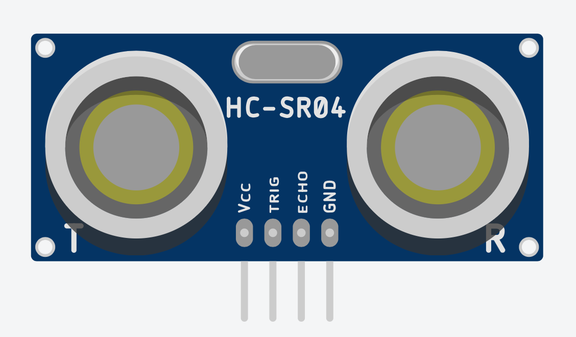
The ultrsonic sensor we are going to use is the HC-SR04, which is commonly used in Arduino circuits:
Note that we need to use the 4 pin sensor instead of the 3 pin one, which can be found by typing ultrasonic sensor in the component search bar.
Let us go into TinkerCAD and create a new circuit. We are going to assemble it like this:
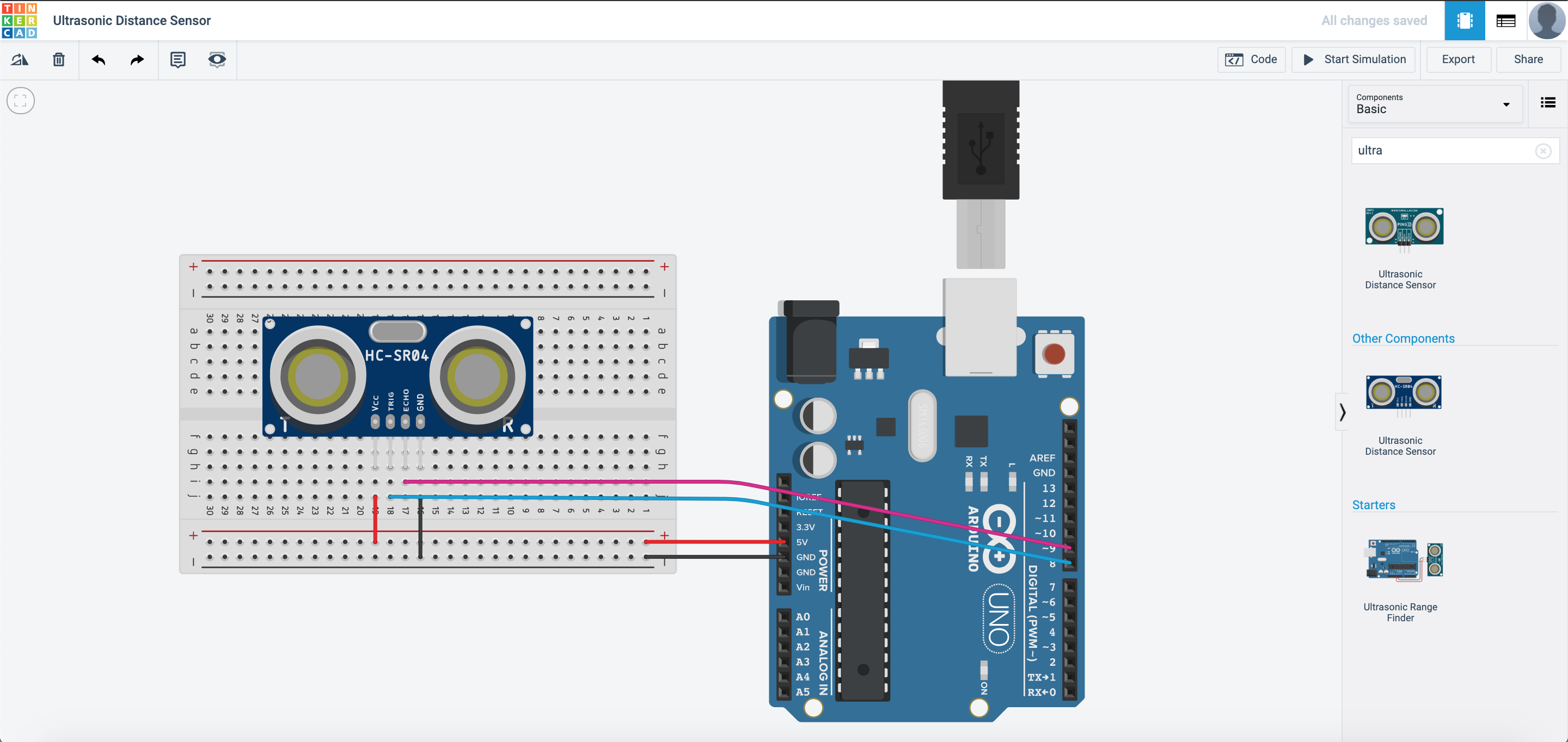
The coding part with blocks is rather simple, as the TinkerCAD team have simplified the code to just this line:

Temperature Sensor
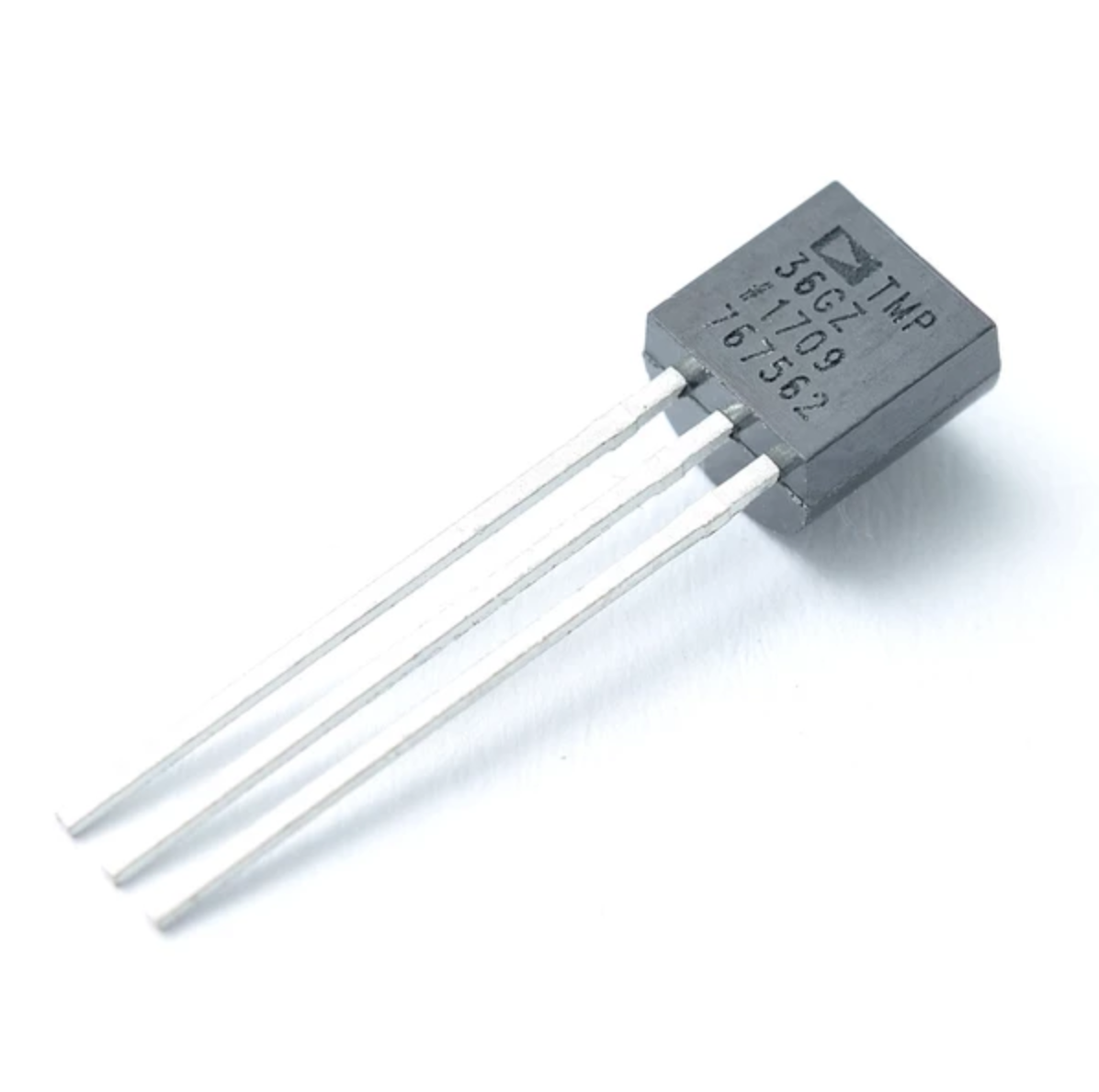
Temperature sensors are essential in electronics. Their uses are very broad, ranging from reading the temperature of the surrounding environment, to the temperature probes on your computer, to keep it from overheating! The temperature sensor that we are going to use in this exercise is the TMP36, an affordable yet accurate temperature sensor.
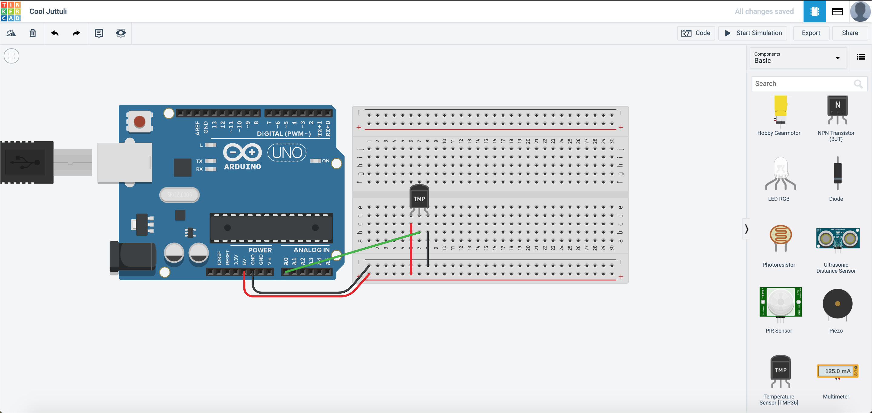
Let us go into TinkerCAD and create a new circuit. We are going to assemble it like this:
The code will look something like this:
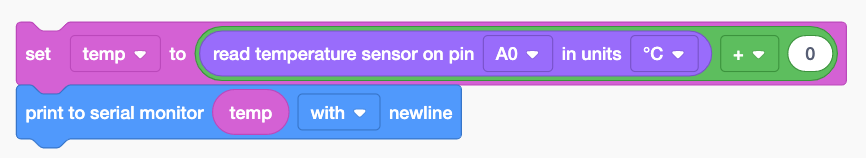
We declared a variable called temp and we let the reading of the temperature sensor be the variable. Next, we add a + sign to it to calibrate the sensor. In the event the sensor reading is lower than the actual reading, we add a few degrees to bring it up.