My first circuit!
In this tutorial, we will attempt a few simple circuits with a simple to use online simulator, TinkerCAD. After which, we will apply the circuits that we have created into real circuits with components in our SSTuino Kit.
Table of Contents
- Hello TinkerCAD
- Sign in to TinkerCAD
- Our First Circuit!
- Your first circuit with the SSTuino Kit!
- Add a button!
- The photoresistor
- Time to turn it up!
Hello TinkerCAD!
Say you have an amazing idea at hand and would like to realise it, to which you are thinking: “Hmm, how can I evolve my idea into a real product?”
Meet TinkerCAD, one of the most popular classroom tools for creating simple designs from scratch. It is a simple to use 3D design tool that requires no downloading of software, as it is an online design program.
In this tutorial, we will go through the setting up process of TinkerCAD and have fun with a mini project!
Sign in to TinkerCAD
Signing in to TinkerCAD is easy.
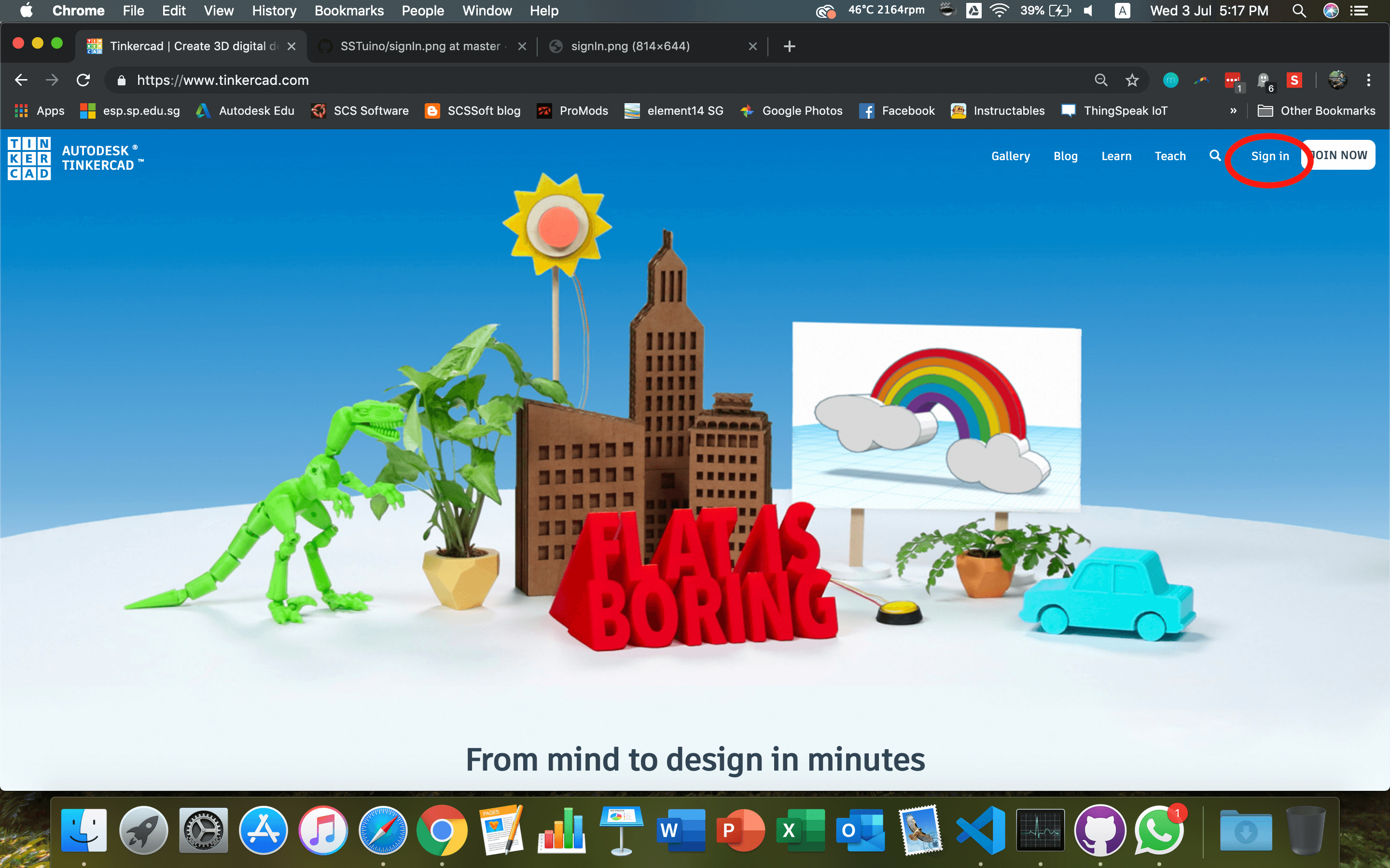
- Go to tinkercad.com and then click on Sign In
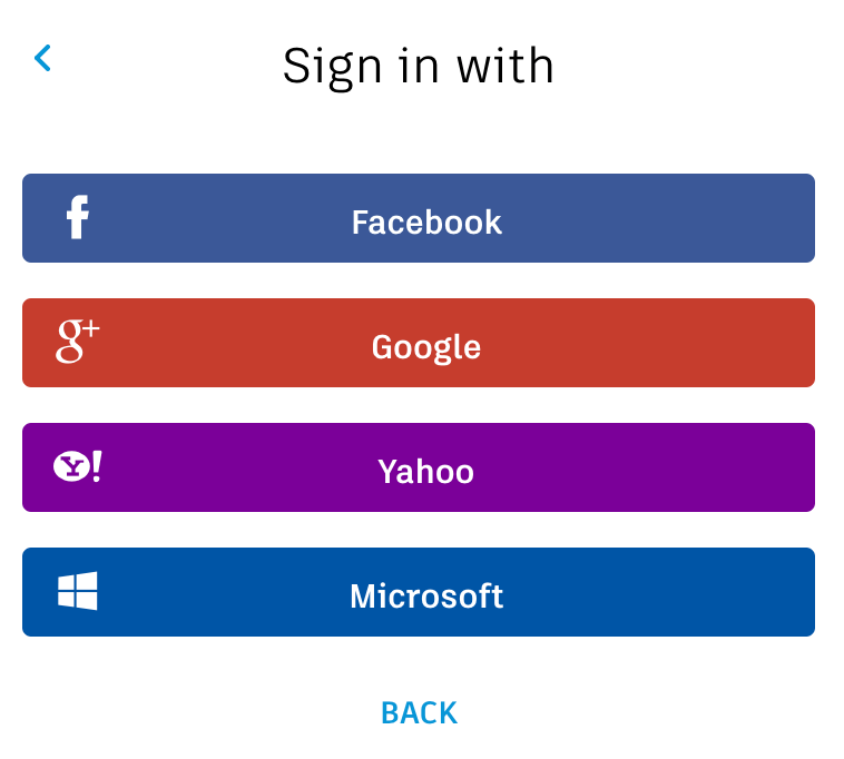
- Go to the login screen

- Select sign in using social provider, and select your Google Account.
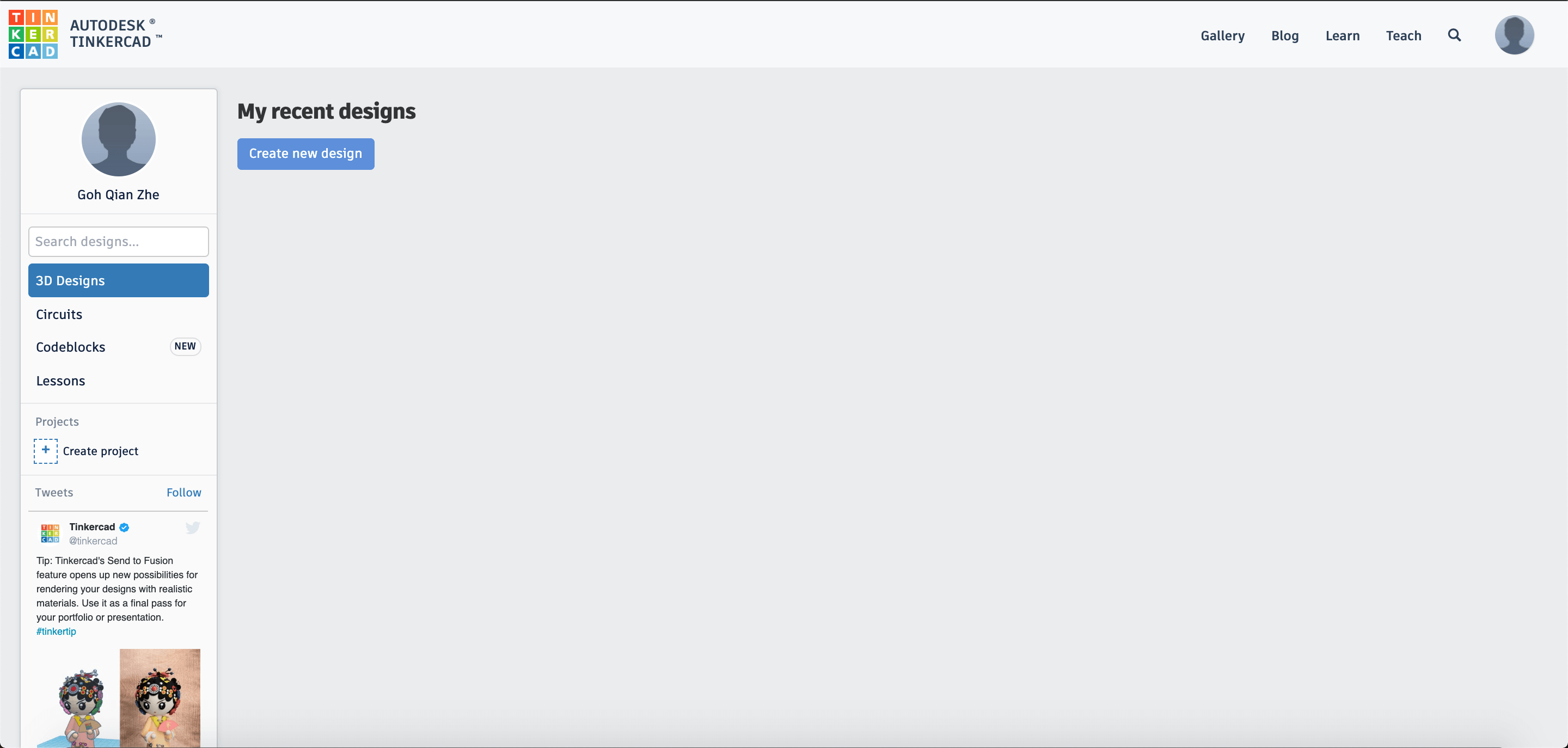
- You are signed in! Your projects will appear here in the future!
Our first circuit!
Back to the topic of burning LEDs, here is one huge benefit of using TinkerCAD. As TinkerCAD can simulate circuits, we can test whether we use the correct components and connected it correctly before actually building it.
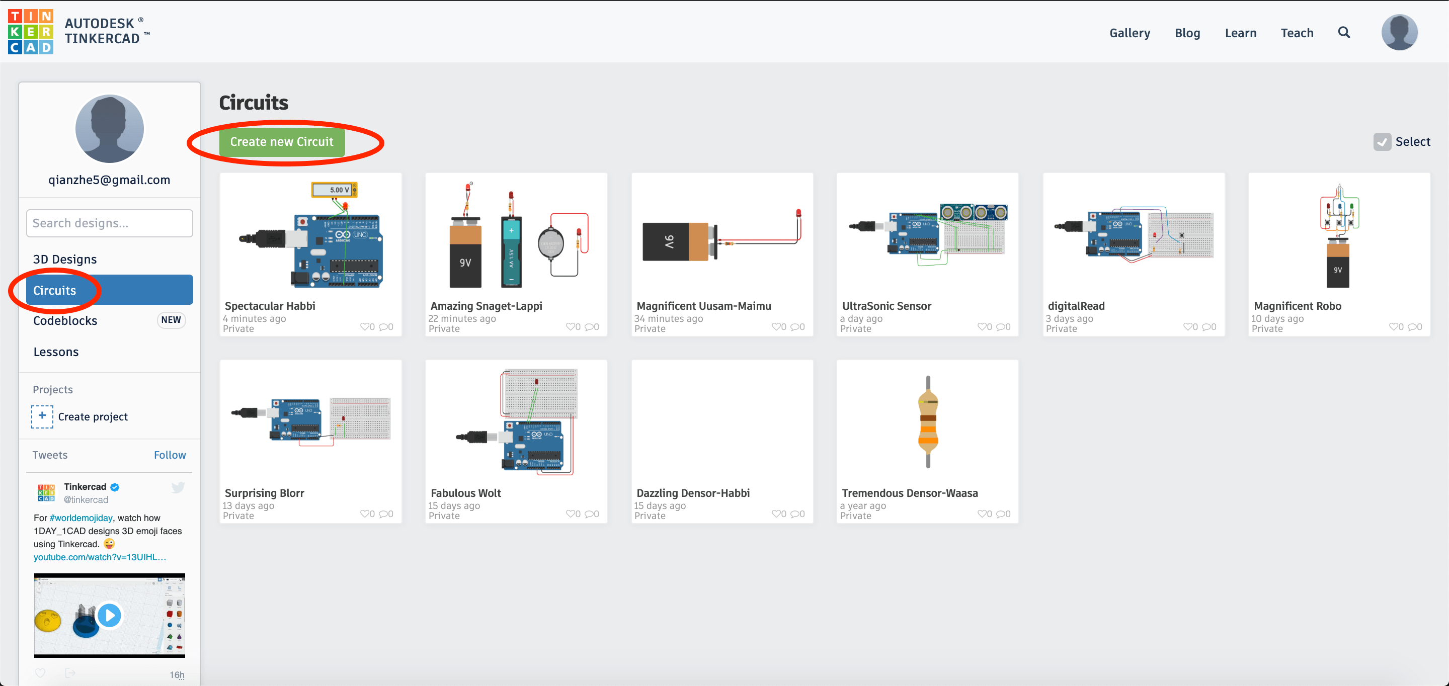
To start building our circuit, after you have logged in to your TinkerCAD account, navigate to
Circuits -> Create new Circuit
It is a very good habit to create a new circuit after you have finished your previous tutorial. This is to help you to be able to remember previous tutorials done when you would like to use it next time. After you have created the new circuit, it should look like this:
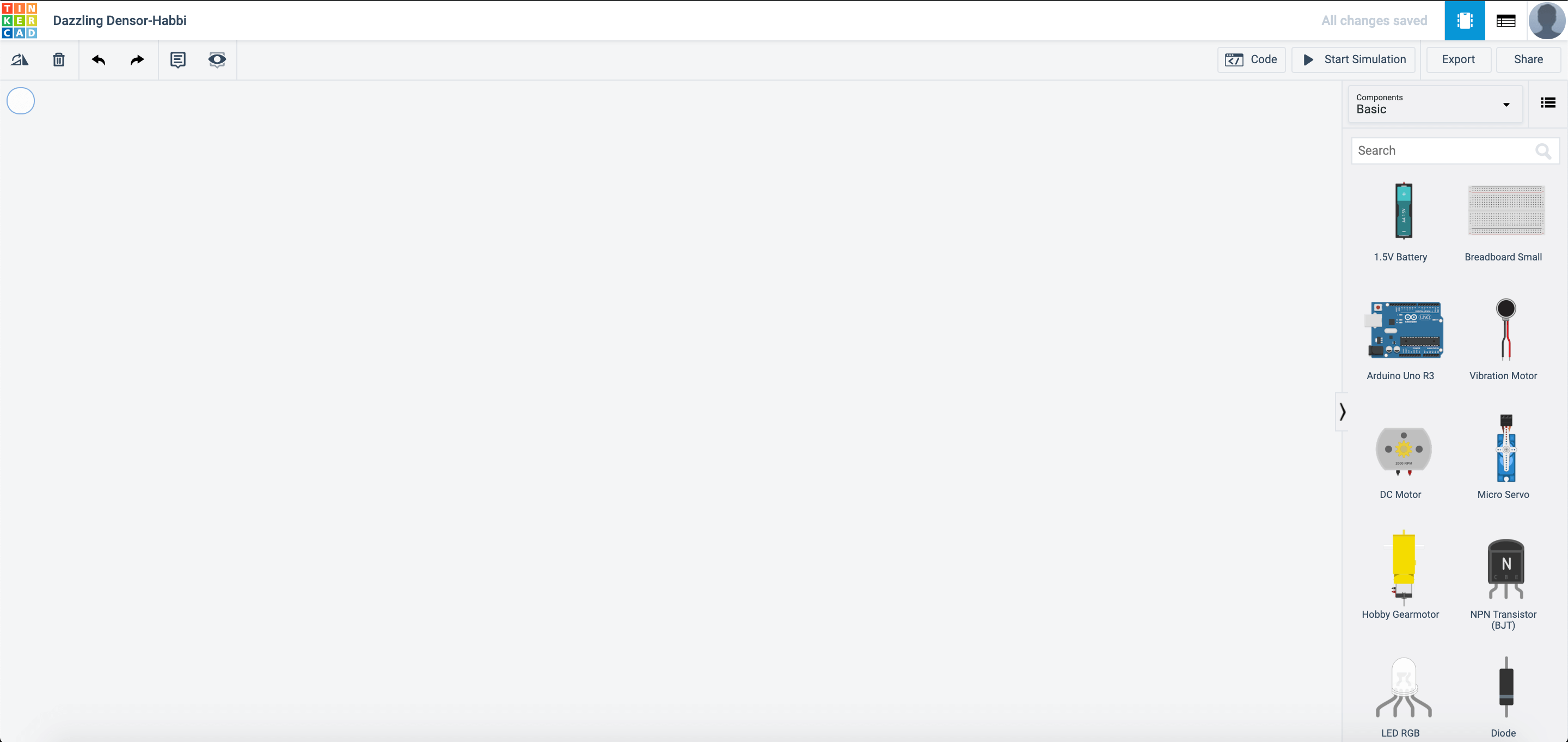
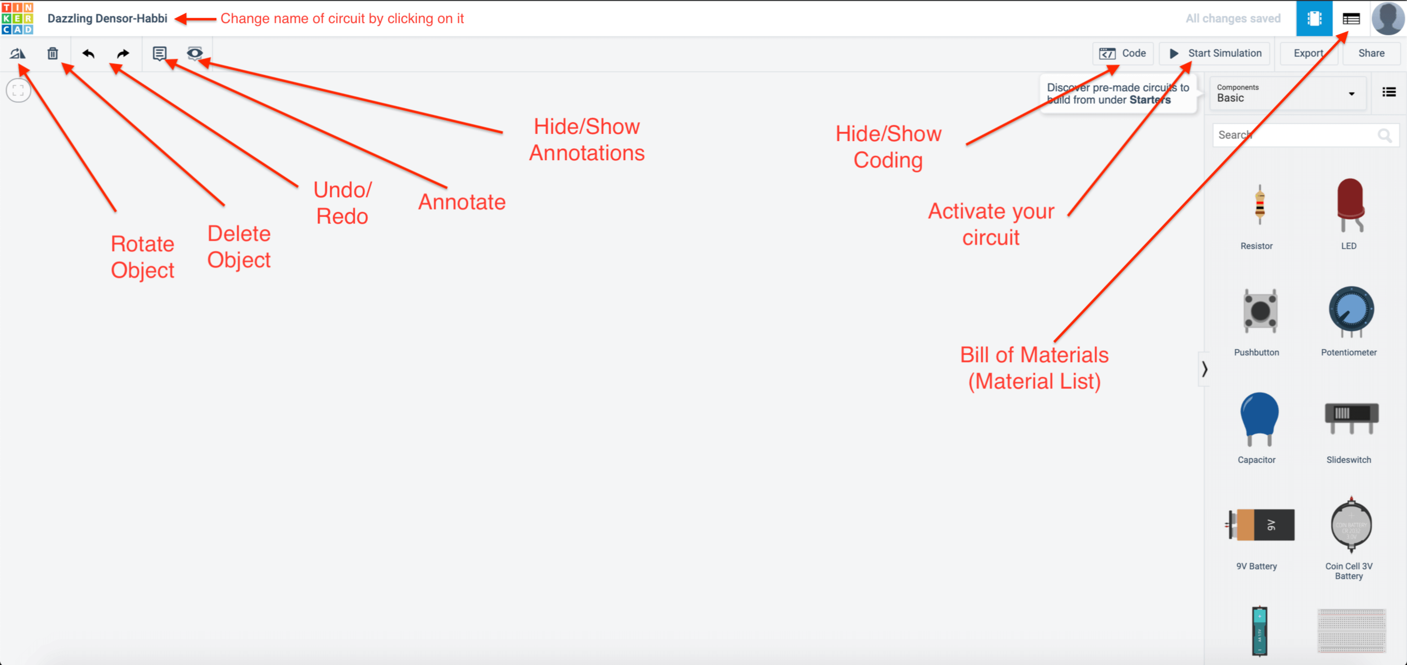
Here are the essential buttons of building electronic circuits with TinkerCAD.
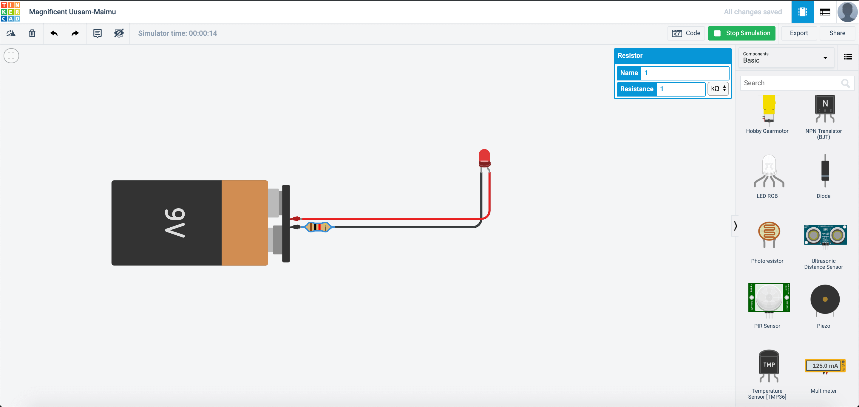
Let us bring out a 9V battery then connect it as follows.
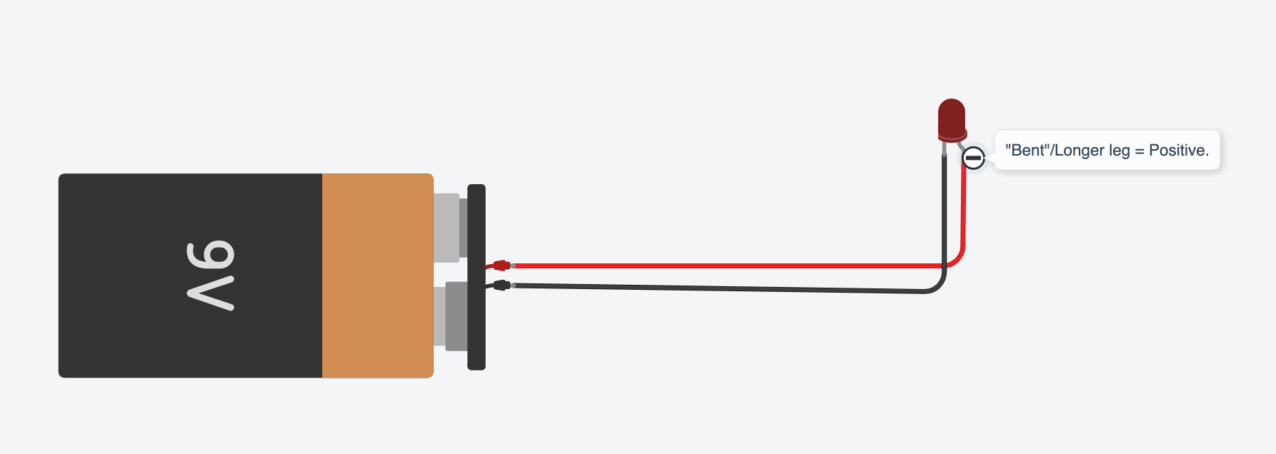
After you have connected the circuit, click on Start Simulation on the top right hand corner of the website.
Once it lights up, this happens.
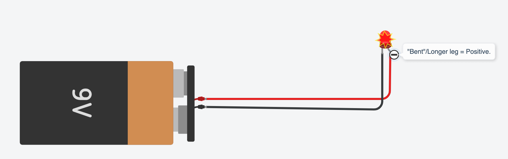
The reason this happens is due to the incorrect resistor being used. Remember Ohm’s Law? When the resistance is too low the current would be too high.
Instead, connect a resistor like this:
With the resistor attached, the LED lights up without burning up. :) Now you try this with different resistor values. What kind of changes happen?
Now, let us try this out using different types of batteries.TinkerCAD mainly provides 3 types of batteries: 9V, 3V and 1.5V. Connect your circuit up as shown.
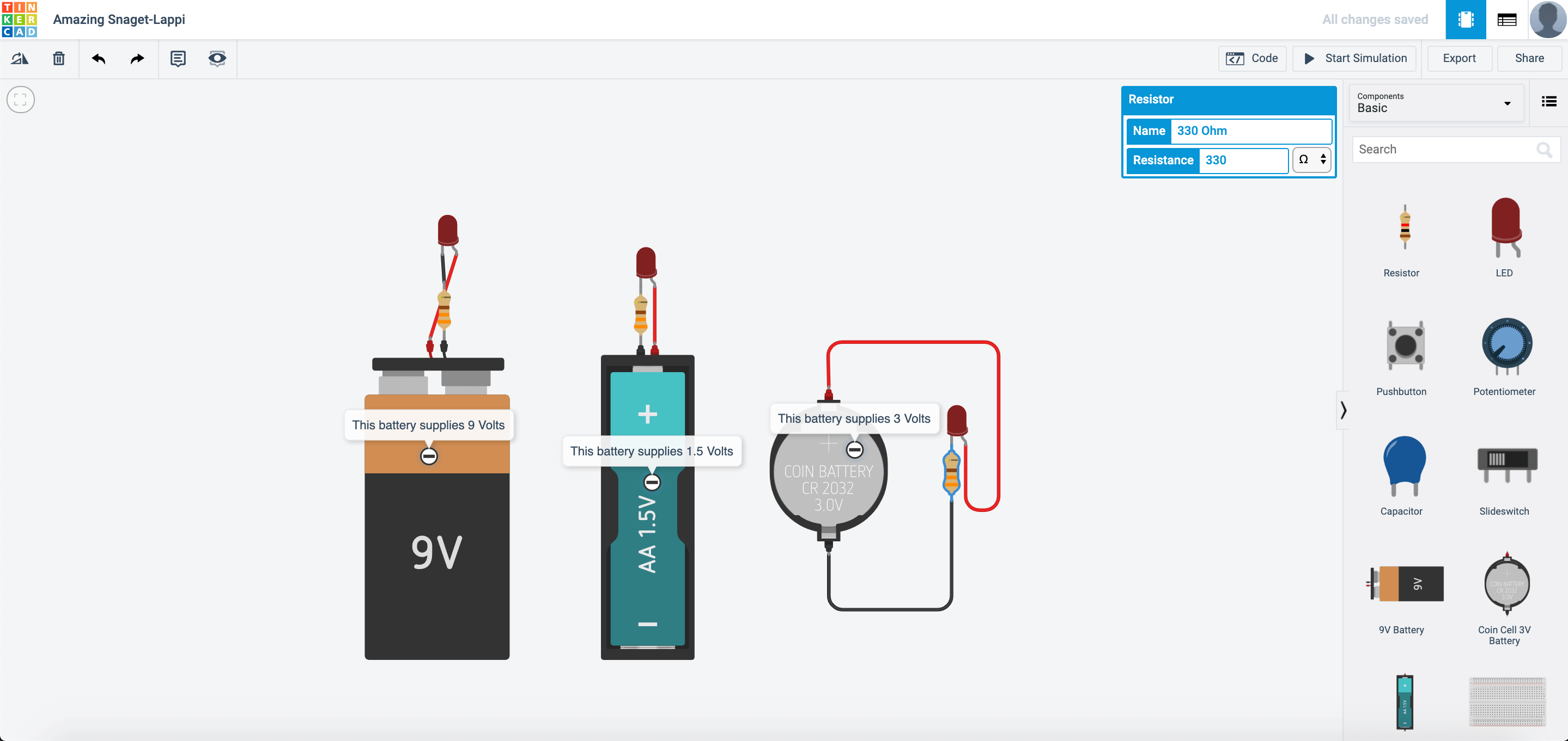
After you connect up the circuit, this happens:
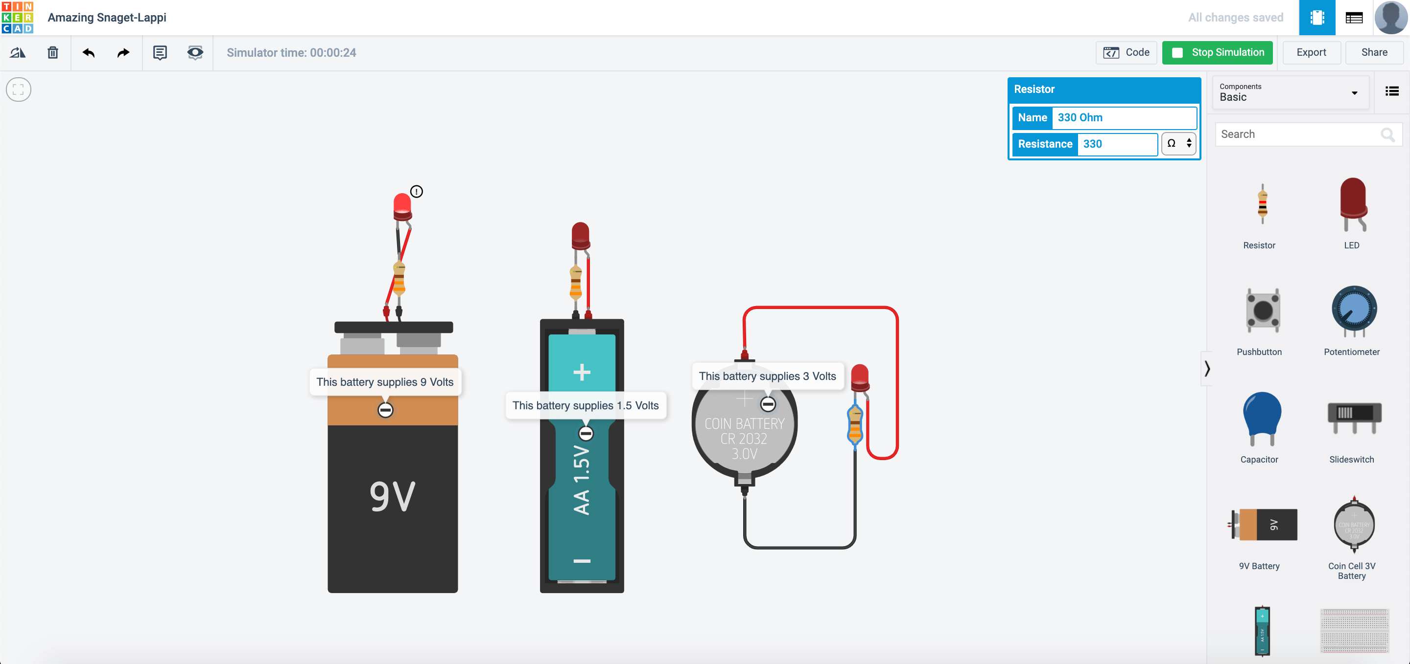
Why would this happen? This is because that LEDs have a minimum voltage to light up. If you look at the spec sheet located here:
https://www.sparkfun.com/datasheets/Components/LED/COM-09590-YSL-R531R3D-D2.pdf
Forward Voltage: Min 1.8V, Max 2.2V. Suggested current:16 - 18mA
This means that the 1.5V battery would be barely able to light up the circuit, and only the 2 other battery types will be able to light up.
Your first circuit with the SSTuino Kit!
So you have built yourself some very simple circuits. Now let us build circuits, but with an Arduino!
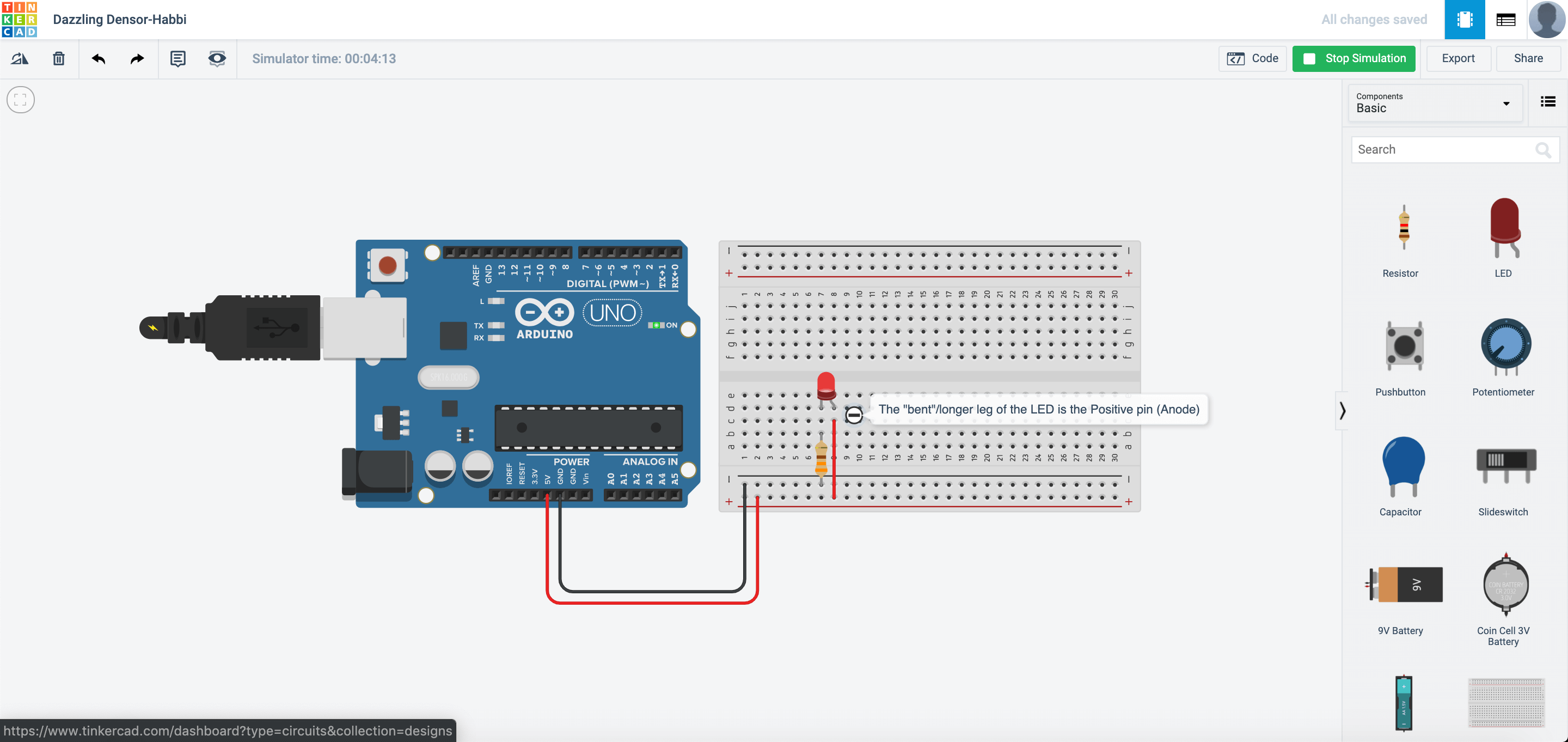
In TinkerCAD, create a new circuit. In this new circuit, drag out an Arduino Uno, a breadboard, one resistor and a LED. Connect it in this manner, with the Positive(+) connect to 5V and the Negative(-) connect to GND.
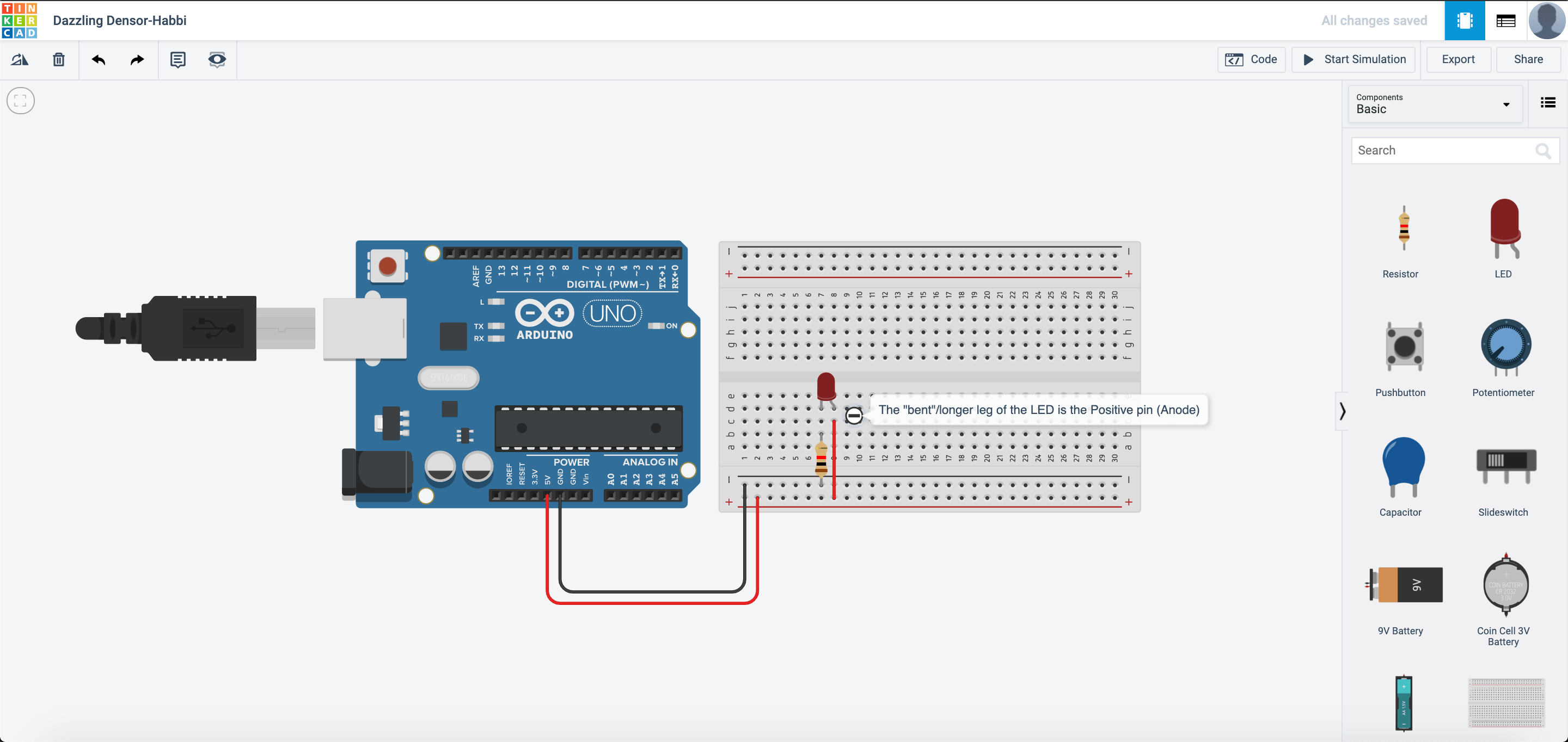
If you had read this tutorial, you should have known how the breadboard works.
Press Start Simulation and see your circuit light up!
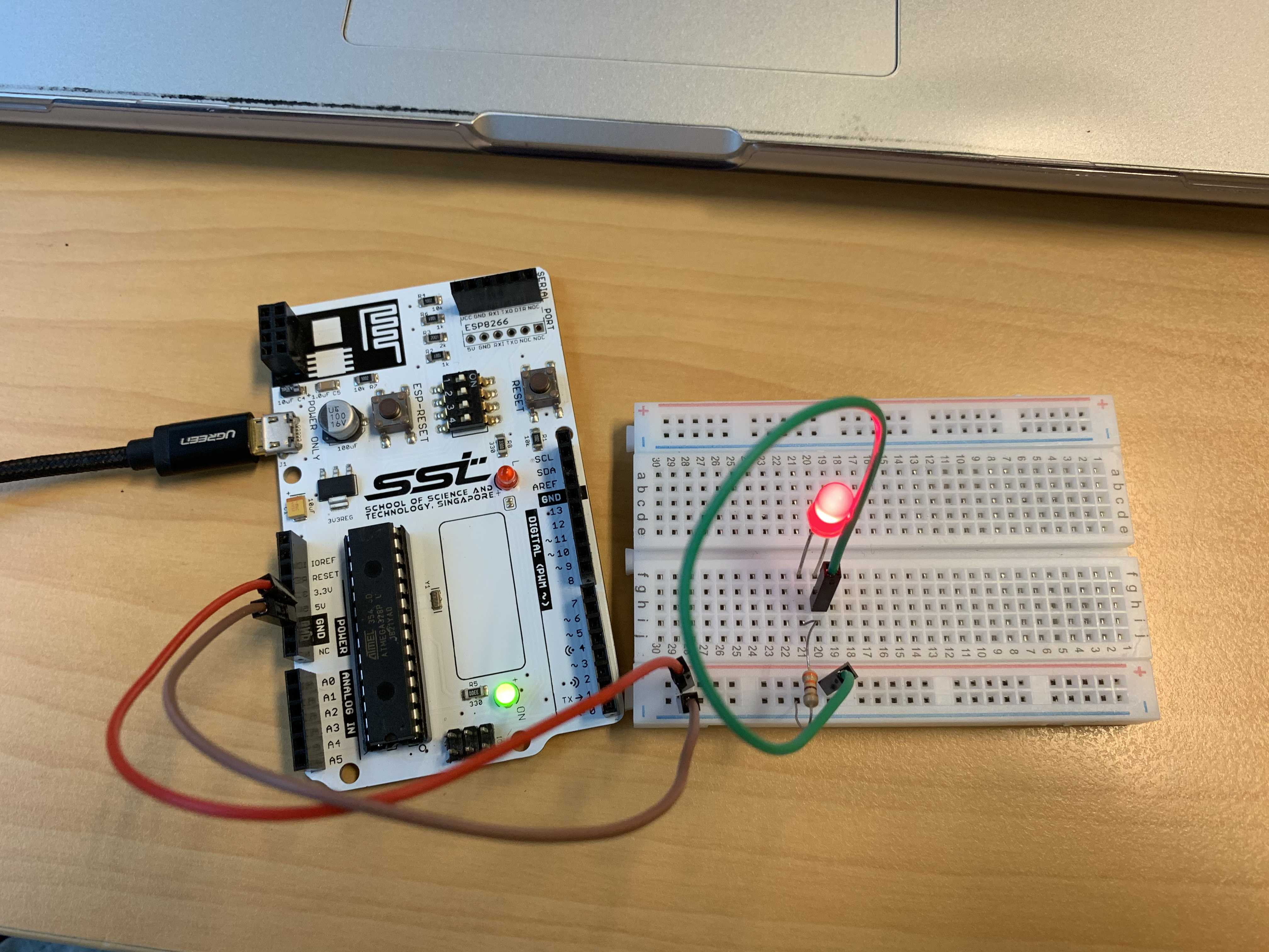
Now, copy your circuit from TinkerCAD onto your SSTuino Innovator’s Kit.
NOTE: To prevent damage to your computer or the components, please disconnect all power from the SSTuino board when you are wiring up your circuit!
It should look something like this:
Let us go back to the simulation and change the circuit like this:
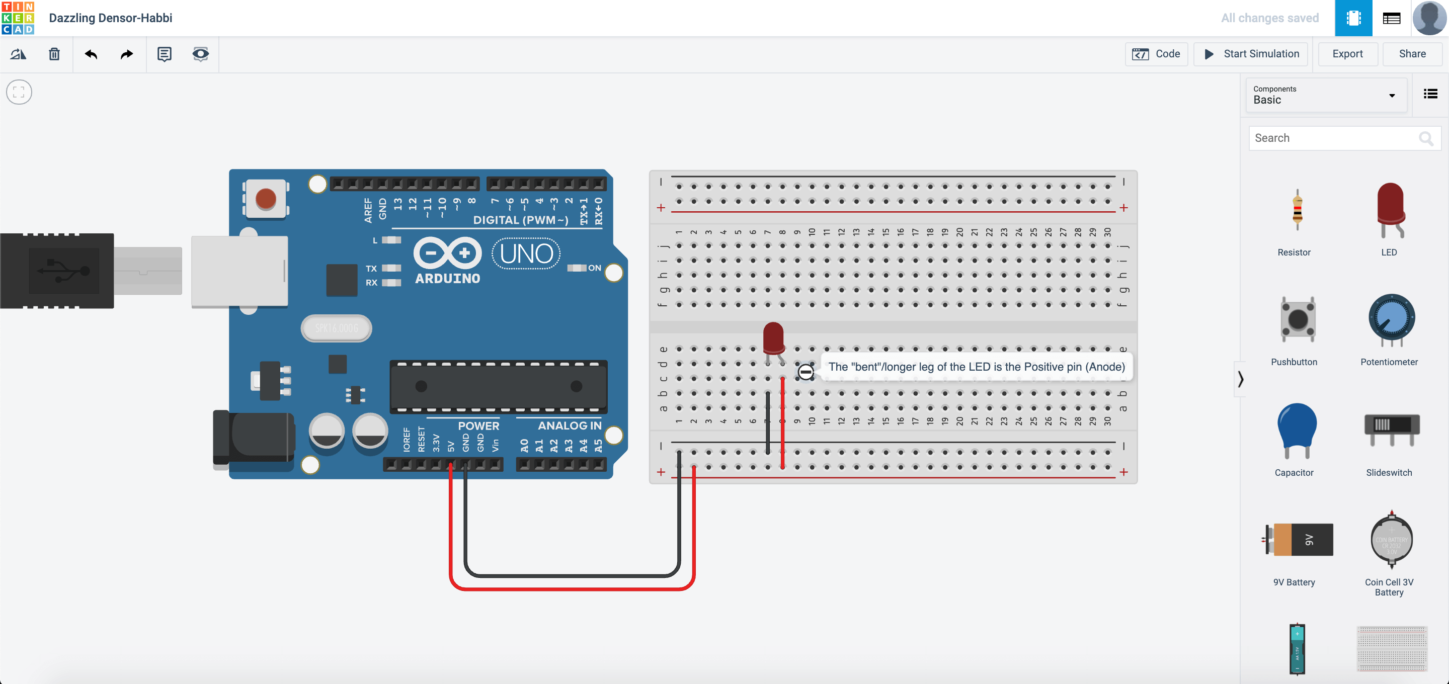
What would happen and why?
Add a button!
Now time for you to “control” your circuit. Set up your circuit like this:
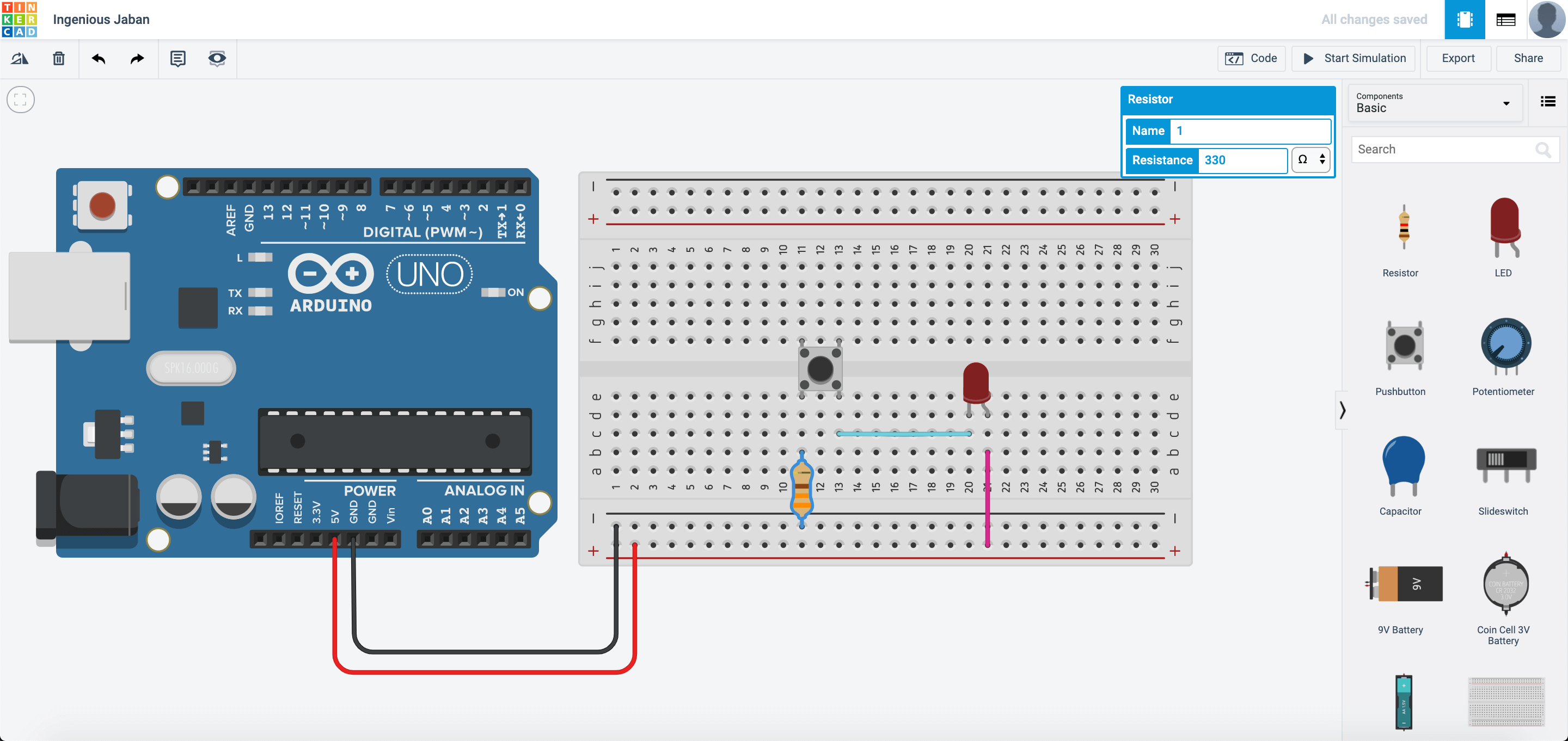
What this circuit allows you to do is to turn on and off your LED. This push button works something like this: When you press the button, the circuit is closed and current can flow to the LED, which makes the LED light up. When the button is not pressed, the circuit is considered open and current will not flow to the LED, which makes the LED not light up.
Copy this circuit over to your SSTuino board setup.
NOTE: To prevent damage to your computer or the components, please disconnect all power from the SSTuino board when you are wiring up your circuit!
To futher spice up your circuit, you can consider adding more LEDs to the circuit. How would you add the LEDs to the circuit? What kind of reaction does your circuit have?
The photoresistor
The photoresistor is a resistor that reacts to light. It changes resistance when the amount of light it detects changes.
Create a new circuit and set up your circuit like this:
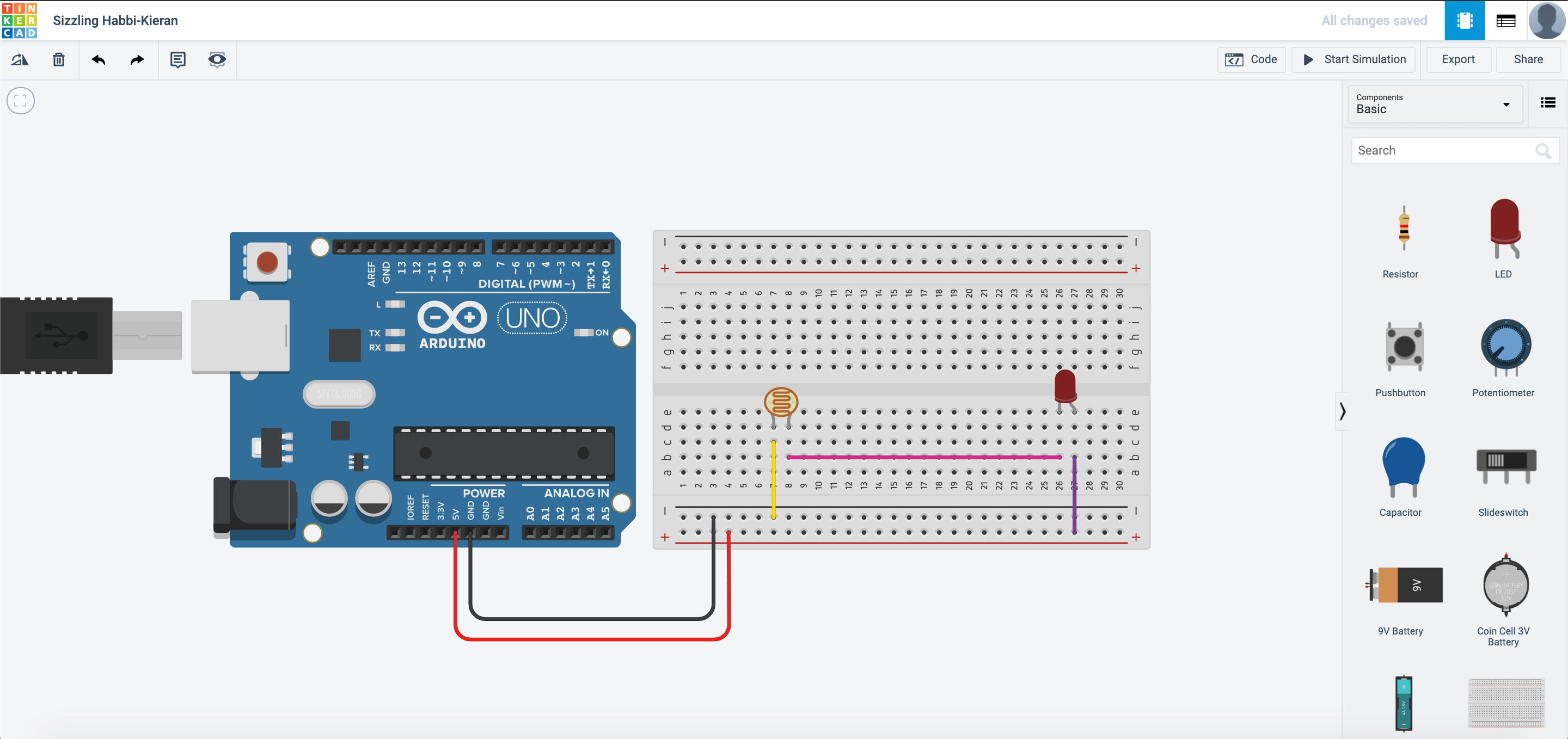
What this circuit allows you to see is the difference in LED brightness as you cover the photoresistor or shine a torch on it.
Copy this circuit over to your SSTuino board setup.
NOTE: To prevent damage to your computer or the components, please disconnect all power from the SSTuino board when you are wiring up your circuit!
What happens to the LED brightness as you play with the photoresistor? Record and post a video onto Instagram and place a hashtag #sstuino!
Time to turn it up!
We are going to move into the programming stage of the SSTuino Innovator’s Kit, so please move to the next tutorial